Wednesday, 19 December 2018

How to use CGR mode for large assembly visualization in CATIA


Hello Friends,
Welcome to "Design Tech Academy".
In this post, i will tell you setting to change Design mode to CGR mode for large assembly for fast process or fast loading.

Many time we face problem with large assembly which takes time for loading but we don't require to load all parts of assembly so we have a good option for load only selected parts as per your need in CGR mode.
*CGR Mode:- Catia Graphical Representation
Its a representation method without loading parts (visual only)

Follow simple step to change settings:-

1st:- Tools -> Options


2nd:- Infrastructure -> Product structure -> Cgr management -> General
Check (Select) highlighted option for start cgr mode for large assemblies.
Select Ok for save updated settings.


Watch CATIA Tutorial:-


How to stop auto synchronize all external links when updating in CATIA

Hello Friends,
Welcome to "Design tech Academy".

In this post i will try to share about changing Synchronize settings in CATIA.
Many time we face problem with CATIA when we open part but due to some links update it auto synchronize and become red till full update.

So it can be change by some simple steps:-

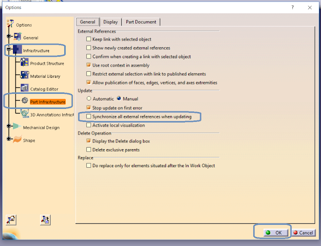
1st- Tools-> Options.


2nd- Infrastructure -> Part Infrastructure-> General -> Update.
Uncheck highlighted below option from dialog box and select ok to save updated settings.


Watch CATIA Sketching tutorials classes:-


Tuesday, 18 December 2018

How to change updating (Automatic/ Manual) in CATIA and stop update at first error


Hello Friends,
Welcome to "Design Tech Academy".
In this topic, we will change the settings for updating parts (Automatic/Manual) in CATIA and stop updating at first error.

Follow simple steps for change setting:-

Step1st:- Tools-> Option


Step2nd:- Infrastructure -> Part infrastructure -> General.

For update setting:- Select from Automatic or Manual for update.

For stop at error:- Check the option (underline option) for stop at first error at the time of error.


Select OK for save changes.


Watch video for CATIA Practice:-


Thursday, 8 November 2018

CATIA Setting:- How to add Shortcut key on Commands (Shortcut for Hide/Show command)


Hello friends,
When we use CATIA, at that time we require lot of commands (tools) to make our design and for fast process we require some shortcuts for commands which helps to work fast on CATIA.

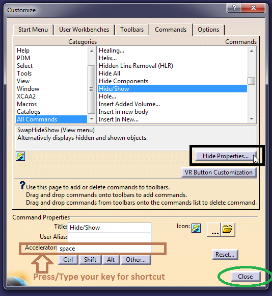
In this Post, i will share the method to add shortcut of any command in CATIA and for example we will add a shortcut for Hide/Show command.

"For hide and show we require Right click then we select Hide/Show which time taking" so we will add shortcut for it.

Follow Some simple steps to add shortcuts:-

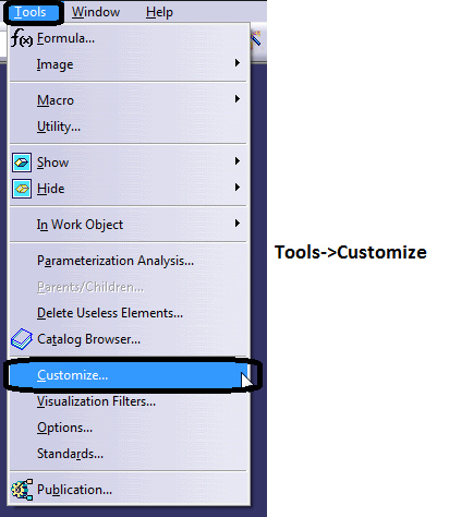
1st- Tools-> Customize


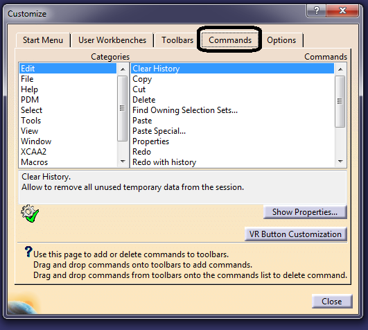
2nd- In Customize-> Commands


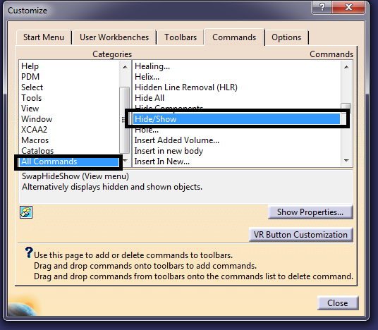
3rd- Select command from Right side and Categories from Left side.


4th- After selection of command, Click on "Show Properties".

5th-  Select "Accelerator" And fill Command name/Press Key for Shortcut.

Ex- "Space" Type by manully for space key from keyboard.
You can select "H" or other also as per your need.


For Reset, Press Reset.

And for save Change, just close .


For Study 

Saturday, 27 October 2018

CATIA Setting:- How to add Design module in workbench


Hello Friends,
In this post, we will learn, How to add Design module (Part Design, G. Surface....Assembly) in Workbench for easy to switching between them.
As like shown in Below attached pic.


Follow Some simple steps:-

1st- Go in Tool-> Customize........


OR
Right Click on Status bar area and select from Dialog Box.


2st:- Go at Start Menu and Add Favorites Design Mode from Available List.

For Adding-
Select Mode and Press -> 
For Remove 
Select Mode and Press <


For Save Updated Setting Press Cancel.


Saturday, 20 October 2018

CATIA Tutorial :- What is Federation and How to use it in Join Command


 Federation is useful grouping feature.
Federation is grouping elements (surfaces and curves) in a Join for easy picking later.
Exmple:- Group/Blocks use in AutoCAD/Drafting.
Federation Only can be found in “Join” and “Extract” command in CATIA (Generative Shape Design Workbench).

Let's try to understand its use in Join Command:-


  • We have 5 Surfaces here.


  • We are Joining Surfaces with Federation.
  • Check Below attached pic to go on Federation option.


  • Selecting 3 Faces in Federation. (Face 1, Face 2 and Face 3)

  • Join Reflected Federation Option used.


  • If we will try to Extract any face (From Federation faces) then it will Select it in single element due to Federation option.
This Effect (Grouping) Comes by the Federation option in CATIA.


Without Federation option Joining Command :-


  • It Treat it into separate element.


Result Defference In Join Federation

If we will Compare between Extract Result of Join With Federation and Join with out Federation then we will get below attched result.  


Subscribe youtube channe for technical videos :-  Design Tech Academy

Visit for more technical notes and support. For plastic design :- Plastic Design For CATIA:- CATIA Tutorials For SolidWorks:- SolidWorks Tutorials For GD and T :- GD and T

Some Video Tutorials:-


Saturday, 8 September 2018

CATIA Setting:- Increase the Number of undo in CATIA

This is possible to Increase the number of undo in CATIA and this is possible trough Settings available in CATIA.

Follow Steps:- 
Step 1:- select Tools menu 


Step 2nd:- Options General PCS tab.

Undo controlled by Stack Size So Change the number of Stack Size for Change number of undo in CATIA.

Select OK to Apply Settings.


Video Tutorial:- 


Monday, 3 September 2018

Basic Introduction of Aerodynamics


Introduction
AERODYNAMICS WORD WAS TAKEN FROM  GREEK.
ἀήρ aer (air) + δυναμική (dynamics)
Formal aerodynamics study in the modern sense began in the eighteenth century.

DEFINITION OF AERODYNAMIC
The study of the motion of air and other gases and of the effects of such motion on bodies in the gas.

History of aerodynamics
In 1726, Sir Isaac Newton became the first person to develop a theory of air resistance,making him one of the first aerodynamicists. Dutch-Swiss mathematician Daniel Bernoulli followed in 1738 with Hydrodynamica, in which he described a fundamental relationship between pressure, density, and velocity for incompressible flow known today asBernoulli's principle, which provides one method for calculating aerodynamic lift.
In 1799, Sir George Cayley became the first person to identify the four aerodynamic forces of flight (weightliftdrag, and thrust), as well as the relationships between them.
The Wright brothersOrville (August 19, 1871 – January 30, 1948) and Wilbur (April 16, 1867 – May 30, 1912), were two American brothers, inventors, and aviation pioneers who are credited[.with inventing and building the world's first successful airplane and making the first controlled, powered and sustained heavier-than-air human flight, on December 17, 1903. From 1905 to 1907, the brothers developed their flying machine into the first practical fixed-wing aircraft.

FORCES
1.LIFT
2.WEIGHT
3.THRUST
4.DRAG


THRUST FORCE
oThrust is the force produced by the engine. It is directed forward along the axis of the engine.

Drag FORCE
oDrag is a component of the aerodynamic force, namely the projection onto the direction parallel to the relative wind.

Lift FORCE
oLift is another component of the aerodynamic force, namely the projection onto the two directions perpendicular to the relative wind.

Weight
oWeight is the force of gravity. It is equal to the mass of the airplane times the local gravitational acceleration.

Flight Condition


Sunday, 2 September 2018

Introduction of Automobile

What is an Automobile??

automobile is a wheeled motor vehicle used for transportation (from one location to another).

OR

A self-propelled vehicle powered by an IC engine/Steam engine/Electric motor, used for transportation.


Brief History

  • Around 1672- Ferdinand Verbiest, a priest from China built the first steam-powered vehicle (toy car) for the Chinese Emperor. 
  • Around 1769, Nicolas-Joseph Cugnot, Built the first self propelled (steam-powered) road vehicle (military tractor) for the French army.
  • In 1885, Karl Friedrich Benz from Germany built the first gasoline automobile powered by an internal combustion engine.
  • In 1888, a German inventor Andreas Flocken presented Flocken Elektrowagen - the first real electric car of the world.


Chassis
Suspension and Steering System
Transmission System
Braking System
Fuel Supply System
Engine
Electrical and Electronics

Changes over the years..
Brakes (By Frederick William Lanchester in 1901)
Aerodynamics
Automatic Transmission
Electronic Indicators (1939)
Air Conditioning (1940)
Power Steering
Seat Belts (1956)
Air Bag (1971)
Greater use of plastic
AWD
ABS
EFI
Computer Diagnostics
GPS

Indian Automobile Industry
The first car ran on Indian roads in 1897.
An embryonic automotive industry emerged in India in the 1940s. Hindustan was launched in 1942, long time competitor Premier in 1944.
Mahindra & Mahindra was established by two brothers in 1945, and began assembly of Jeep CJ-3A utility vehicles. Tata Motors also began in 1945.
The growth was relatively slow in the 1950s and 1960s due to nationalization and the license raj which hampered the Indian private sector.
In 1980s, Suzuki and Toyota of Japan and Hyundai of South Korea, were allowed to invest in the Indian market ultimately leading to the establishment of an automotive industry in India.
To promote the auto industry the government started the Delhi Auto Expo which had its debut showcasing in 1986.
As India began to liberalize their automobile market in 1991, a number of foreign firms also initiated joint ventures with existing Indian companies.
Today the automotive industry in India is one of the largest automotive markets in the world.
The majority of India's car manufacturing industry is based around three clusters in the south, west and north with revenue share of 35%, 33%  and 32% respectively.


Thursday, 14 June 2018

Press Operation -2 (Piercing, Straightening & Trimming )


Press Operation

Piercing Practically the same operation as blanking, Except it is limited to holes or slots in sheet metal. The piece cut out is the scrap.


Straightening: - Operations used to make Sheet Straight.


Trimming – Operation on drawn or formed parts to remove excess metal on the flange or axial length.


Wednesday, 6 June 2018

Press Operation -1 (Blanking, Punching & Bending)


Blanking:-

Blanking is a metal fabricating process, during which a metal workpiece is removed from the primary metal strip or sheet when it is punched. The piece cut out is the useful part (Workpiece).


Punching:-

Punching is a forming process that uses a punch press to force a tool, called a punch, through the workpiece to create a hole. The Remained piece is the useful part (Workpiece).


 Bending:-

Sheet metal bending is the plastic deformation of the work over an axis, creating a change in the part's geometry


For CAD Tutorials Subscribe :- Youtube Channel
How to Measure Internal Volume of any part (Capacity of Bottle)