Showing posts with label Plastic Part Design. Show all posts

Thursday, 8 September 2022

Welding Processes for Plastics


 Welding processes for joining plastics are numerous – a selection is listed below.


 1. Laser Welding or Laser Beam Welding (LBW)

Also known as Laser Beam Welding (LBW) this welding technique is used to join pieces of thermoplastics using a laser. The laser beam delivers a concentrated heat source permitting narrow and deep welds with high welding rates whilst the two parts are put under pressure. Speed and precise control are two of its many benefits.

2. Ultrasonic Welding

Ultrasonic plastic welding is a commonly method that has been in use for a long time. It uses the heat generated from high-frequency mechanical motion to join thermoplastics. It happens by transforming high-frequency electrical energy into a high-frequency mechanical movement. You can use ultrasonic welding on almost all plastic material. It is known for being affordable, clean and meeting quality requirements.

3. Hot Gas Welding

A commonly used welding process for the manufacture of smaller items (heat exchangers, chemical and water tanks…), hot gas welding used a specially designed heat gun. The hot air that the gun generates softens the plastic parts to be welded and the plastic filler rod which needs to be of same or comparable plastic material. Also added to the weld joint in addition to the hot gas is a plastic filler material to aid the bonding process.

Ads

4. Spin Welding

For the joining of plastic components, spin welding uses surface friction focussed in a circular weld joint. It produces the heat needed for the melting of the surfaces to be joined by spinning one of the parts relative to the other. The two parts are held under a controlled load. When the spinning stops the joint will be left to cool.

It can be used to weld plastic components of big sizes and is a fast process but one of the parts needed to be circular. One of its uses is the sealing of containers.

5. Vibration Welding

Vibration welding, also called linear or friction welding, is when two plastic pieces are connected under pressure. The heat is generated when a vibration is used along the common interface. Compared to hot plate welding, it is much faster and more accurate.

6. Hot Plate Welding

One of the oldest process, this is a thermal welding technique used for joining thermoplastics. In order to melt two surfaces, a heated metal plate is placed against or near and the surfaces are connected together under pressure. This method is simple and produces strong joints in most all thermoplastics so it is commonly used in the mass production or large structures such as plastic pipes of large diameter.

7. Friction Welding

Friction welding of thermoplastics is often employed for joining injection-moulded parts and was established some time ago. It uses friction to produce heat and to join two pieces together. Friction welding delivers many benefits to manufacturing and is often used in the aerospace and automotive industries this technique to join metals and plastics.

8. Frequency Welding

This plastics welding technique, also known as high-frequency welding or radio-frequency welding, uses electromagnetic field to join two plastic parts. The high-frequency electric fields are used to heat the material and pressure is also added to soften and join the two materials together resulting in a strong bond. Polyurethane and PVC are welded with this technique.

Where is it Used?

There are many types of plastic and it is a versatile material used in a wide range of sectors such as packaging, electronics, construction, fabrication, medical, aerospace, automotive and many other industries. When correctly applied, plastics welding can be enormously strong.

Some video:-


Ads:-


Saturday, 11 September 2021

Plastic part design Rules

Overview:- The following is a summary of the design rules covered in both Designing Injection Molded Parts and this course. Keep in mind that these rules are more or less guidelines intending to help you design parts that can be successfully molded. In extreme cases, it is possible to bend or even break some of these rules. You should consult a tool designer to determine the mold capabilities available for your design.

Wall Thickness:-

 Maintain uniform wall thickness as much as possible.

If you have not yet determined a material, a thickness of approximately 2.25 to 3 millimeters (.09 to .12 inches) is a good starting point.

Typical wall thickness' based on material are outlined in this table. 

When changing wall thickness, do so gradually over a distance of at least three times the change in thickness. Use a radius for a smooth transition.

When changing the wall thickness, do not exceed 25%.

Draft:-

 Always add draft to the walls of a part. Draft can be as small as 1/4 degree, but many materials require more.

Add more draft to walls greater than 25 millimeters (1 inch) in depth.

Add a minimum of 5 degrees for textured surfaces. Some texture may require more.

Undercuts:-
 Add draft to undercut surfaces to easy operation of slides or lifters. 

Plan for cosmetic blemishes formed by slides and lifters. 

Openings:- Ensure there is a minimum of at .125mm, or .005in, for the contacting steel to pass for a shutoff opening. An angle of 3 degrees is preferable. 

Bosses:- 
Add Draft to the inside and outside walls of a hollow boss whenever possible.

Blend the outside corners using a radius of 25% of the nominal thickness.

The thickness should be 50% - 75% of the nominal thickness.

For use with self-tapping screws, the outer diameter should be 2-1/2 times the major diameter of the screw.


Holes:-
 Limit the depth of a hole to twice its diameter.

Ribs:- The thickness should be 50% - 75% of the nominal thickness. 

The height should be limited to 3 times the nominal thickness.

Ensure the top of a rib is at least 1mm (.04in) in thickness.

Blend the base of a rib 25% of the thickness.

Blend the top of a rib at least .25 mm (.010in)

Space multiple ribs apart by at least twice the nominal thickness.


Snaps:- 
Define the angle of the sloped surface on the back of the snap appropriate for either a non-locking or self-locking snap. 

Living Hinges:- 
Use a flexible material such as polypropylene or polyethylene.

Consider secondary operations such as coining or flexing the hinge while the part is hot to enhance the hinge's strength.

Thursday, 9 September 2021

Designing plastic parts for strength

 Overview:  Interior trim parts must withstand substantial pressure and stress specifically parts such as door panels and handles. This document explains various design options to help strengthen the part.


Plastic Filler Materials: Some plastics have fillers added for additional strength. These plastic types tend to be strong however, they can wear out the mold. These fillers have a tendency to wear out mold components like gates, runners, and manifold systems. They can also have effects inside the mold when having to flow around sharp corners or into small features. Some mold vendors prefer to place inserts into high wear areas making the area in question easy to replace. This tends to add more cost to the mold, but can save in the end by reducing the need to completely rebuild an entire mold.

Using Ribs for Strength: Using ribs is probably the most common way to strengthen a part. Ribs give strength to a part and prevent a part from warping. Ribs can be a challenge if they are too tall. You have to be aware of how thick a rib is at the base of the part. Ribs that get too wide at the base can produce a sink mark in the opposite side of the part. This is not good for cosmetic parts because these flaws can be apparent. One consideration is to reduce your rib versus wall thickness percentage. The general rule is to make the rib thickness 60% the thickness of the part. You can reduce this to 50% of the part thickness to help keep the thickness at the base to a smaller size.


ADS
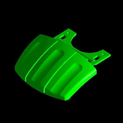
Coring versus Ribs:Sometimes ribs are not the appropriate tool to use. In the following example, a door handle is created and shown with its outer shape. 


In this scenario, the part needs to look and feel as if it is a solid part. The part has a thickness that is too large to mold with a multitude of flaws including sink marks and warping. If you try to shell the part and add ribs for strength, you might create a sharper edge on the backside making it uncomfortable to grasp.

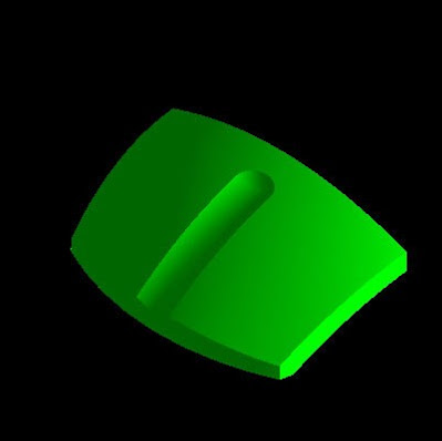
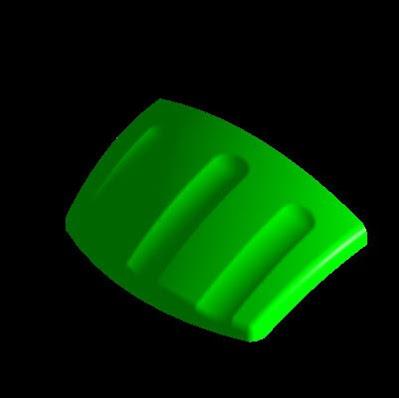
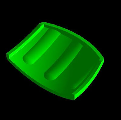
In this situation, coring can be a viable solution. By removing a series of pockets on the backside, you can simulate the feel of a complete part, but have the necessary walls in it to avoid the problems.

Wednesday, 8 September 2021

Plastic part Design CAD process

Plastic Part design CAD process
Overview:  Design requires careful planning during the entire process. Knowing how to use the available tools is the key to creating successful designs.

Conceptualization: Before creating your part, it's a good idea to conceptualize your design. Some designers begin with a 2-D layout or even a rough CAD model, which will be redone. Hand-drawn sketches can even be a tremendous advantage in getting started. Many good designs started as a rough sketch on a napkin. 

Conceptualization


For styled consumer products, many designers sculpt their parts out of clay or Styrofoam before ever attempting to create a CAD model. This can be useful in that you can create a mockup of your part. You can study this crude prototype to determine both how functional and moldable it is. Quite often, the most obvious molding issues are revealed at this stage. Reshaping your part to make it moldable before starting your CAD model saves valuable time.

Orienting the Part: The idea behind conceptualizing is to determine how to approach your CAD model. Think about your part in a mold tool. What features does it have and how are they oriented? Can the part be oriented in the mold tool so that there are no undercuts?

By answering these questions, you can determine the draw direction and parting line for your part. Then you have a starting point for your CAD model. 

Orienting the part


ads
Modeling the Basic Shape: Many models begin by creating a Pad with a Sketch. 


With plastic parts, you should first concentrate on modeling the main portion of your part. That is, the overall shape of the part without the individual features. This portion of your model has a nominal, uniform thickness.

Shape your part by adding additional features. Creating sketches to define split profiles is a good approach. You can Pad or Shaft these sketches to Split the solid body. 


You should already be thinking about draft. Adding Draft features while creating the model in these early stages saves you time when you must prepare your model for tool design.

Padding sketches may not always define the desired shape. You may find it necessary to create surfaces or additional solid bodies. Doing this allows more flexibility in the way you can define the necessary shape. These bodies are commonly referred to as tools. Use these tools to Split or Remove material away from your solid body.


You also need to be thinking about Fillets. Use this feature to eliminate the sharp corners of your model. Fillets are normally added after Draft features.


By concentrating on only the basic shape of the part, you can now use the Shell feature to easily give the part a nominal, uniform thickness. 


Adding Features: Now you can begin adding features such as snaps, ribs, and bosses. The reason for holding off on these features until now is that they typically have a thickness smaller than the nominal thickness. The Shell feature is used to define the nominal thickness, so these features should be added after the Shell feature.


Evaluating the Design: Once you have completed your model, you need to check it. You can use operations such as Measure Between to verify the thickness in different areas. Doing this gives you a chance to catch anything you might have missed. Correcting thickness problems allows you to avoid having to deal with sink marks after the part has started a test production run.


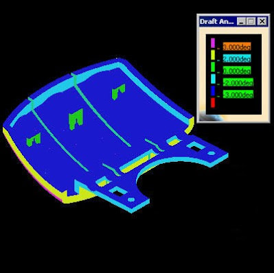
Draft Analysis is another key tool for analyzing your part. This allows you to graphically note the draft angles. It can be quite easy to forget to draft some faces of your model.


Identifying problem areas on your model is an important step in the design process. Once a mold tool is cut, it can be quite expensive to modify. Carefully scrutinizing your design can easily save thousands of dollars.


Sunday, 28 June 2020

Shut-Off Angle for Plastic Parts


Shut-OFF angle for plastic Parts

Overview:- 

Everyone know related to Draft Angle and Parting Line for plastic parts which applicable and standard with all plastic parts but in some condition we have to change some angle to generating clearance to prevent our mold parts which is know as Shut-OFF angle.  

What is Shut-OFF angle:- 

Shut-Off angle is applied for prevent the mold parts (Core and Cavity) from crashing into one another if there is any slight misalignment upon mold parts closing.
Shut-OFF angle also prevent galling that would occur if vertical metal faces were rubbing against each other.

Shut off angle in plastic

Note:- 
  • A draft angle exists for purposes of part release, while a shutoff exists to prevent mold parts.
  • Shut-OFF angle also come there where Parting Line And Tooling direction of mold comes parallel. 

Value For Shut-OFF Angle:-

The Rule for Shut-OFF angle is "Shut-OFF angle must be more then 3 Degree.
Or Misalignment on closing must be .010 minimum.


Type of Shut-OFF Angle:-
There are Fourtype of Shut-Off Angle-
  1. FLAT
  2. WIPES
  3. SADDLES
  4. radiused saddle:


Some Video Tutorials:-


Tuesday, 2 June 2020

Fillet/smooth Corner in Plastic Part Design

Fillet or smooth corner in plastic part Design


Overview:- 

A feature that changes sharp corners or edge into smooth corners is known as Fillet.
Corner in plastic part play important role in plastic design because in corner areas we have to remove sharp edges to uniform thickness,maintain flow of melted plastic and to protect corner from external impact which can defect the plastic part.

Fillet:-

=>In sharp corner areas can form stress concentration and part can failure take place.

For creating fillet there is two type of  condition generated:-

1:- Where we need smooth corner/fillet:-

In plastic part where need smooth corner means fillet we apply directly as per need but for maintaining uniform thickness we have to consider thickness of the parts.
Ex:- If we have 2mm Part thickness and outer radius is 5mm then we have to apply inner thickness as,      
  Inner radius= Outer radius- Thickness of part
                            Inner radius= 5mm-2mm = 3mm

2:- Where we have sharp corner:-


For these corners, where we dont have specify requirement fillet on plastic part at there we have to apply minimum radius for filleting because at the time of injection molding process melted plastic reach late till corners and many time difficult to fill corners due to solidification time/ cycle time which can increase the number of defects and cost of manufacturing. so we have to remove all sharp corners except parting line (corner).

For minimum radius on sharp corner can be 0.3mm to 0.5mm depend upon Material and manufacturing conditions.


Video Tutorials on Youtube:-


Tuesday, 26 May 2020

Tooling Direction for Plastic Part


Overview:-  Tooling direction is main consideration for plastic part and mold parts because it defines movement of mold part and possibility of plastic part to come-out from mold part (Core and Cavity).

ads
Tooling Direction:

  • In Molding machine arrangement is given to open the mold along a direction which is known as Tooling Direction.
  • In other words.  The mold is built from two separate halves (Core and Cavity) and tooling direction basically define the direction of mold pulls apart.
  • Tooling direction is known as primary direction.


Some Video tutorials:-


Friday, 22 May 2020

Thickness (Wall Thickness) in Plastic part.

Overview:-  

One of most important and basic design principle for plastic parts design is thickness (wall thickness/ Nominal thickness).
When designer starts work on plastic then its a most important point which must be considered as per size and shape of part to create economical and easily produced plastic part.

Thickness of part:-  

In ideal practice, Plastic part must having uniform part thickness because uniform thickness allow the mold parts (Core and cavity) to fill more easily. If part don't have uniform thickness then thin section cools first then as thick section cools which can generate defects in part.

For cost savings and high rate of production, plastic parts have a minimum wall thickness because thick parts take more time to fill in molds part and take more time to cool which can increase cycle time and chance of defects also.

On average, the wall thickness of an injection mold parts ranges comes-in between 2mm to 4mm.
But most part can be designed in range of 0.75mm to 5mm thickness.
Ex-
ABS-> 0.75mm-3.18mm
Polycarbonate-> 1mm- 9.53mm
PVC (Rigid) -> 1mm - 9.53mm
Nylon-> 0.38mm-3.18mm
Polypropylene-> 0.64mm-7.60mm
In Above Image, there is no uniform thickness rule implemented so it have this area weak where stress concentration can be.

Thickness Transition:-

In plastic part design, uniform thickness is important but on some places we have change part thickness then we never change it abrupt transition and gradually change but we change it as smooth transition.
Ref- Here we have smooth transition from nominal part thickness to required part thickness.

For change, thickness can be dropped only 25% or less of part thickness.
For best design, there is no change of thickness.
For smooth transition, change of thickness must be in 3X.

X= Required part thickness


Some Video Tutorials:-
                                             

Wednesday, 20 May 2020

What is Parting line in plastic parts??

Overview:- 

Parting line is most important factor in plastic parts and in plastic part design because it defines boundary of mold parts so it plays a important role in it.
Each plastic part have parting line.

 Parting line:- 

Parting line is the line of separation on the plastic part where two halve of mold meets. Actually parting line indicates the parting 'plane' that passes through the part.

  • Ex- Refer Image (1):- Here we have two halve of core and cavity (gray colored parts) and plastic part (yellow Color). Parting line representing separating plane of it.

In simple line, Where mold halve (Core and Cavity) meets with plastic part that line indicates Parting line.
  • Note:- In Image (1)- Core, Cavity and plastic part is meeting at the edge of plastic part which is known as parting line.
ads
 General concept and Design Options:-
  • Parting line defines mold core and cavity.
  • Boundary between positive and negative draft also defined by parting line.
  • Parting line is visible which you can see easily.
  • Parting line is difficult to achieve for complex parts.
  • Often misalignment.
  • Must be consider early in design.
  • At parting line after molding process we get flash also.

Video tutorials:-
1:-CATIA Sweep full video                                   2:- Fan blade in CATIA