 |
| Plastic Part design CAD process |
Conceptualization: Before creating your part, it's a good idea to conceptualize your design. Some designers begin with a 2-D layout or even a rough CAD model, which will be redone. Hand-drawn sketches can even be a tremendous advantage in getting started. Many good designs started as a rough sketch on a napkin.
 |
| Conceptualization |
For styled consumer products, many designers sculpt their parts out of clay or Styrofoam before ever attempting to create a CAD model. This can be useful in that you can create a mockup of your part. You can study this crude prototype to determine both how functional and moldable it is. Quite often, the most obvious molding issues are revealed at this stage. Reshaping your part to make it moldable before starting your CAD model saves valuable time.
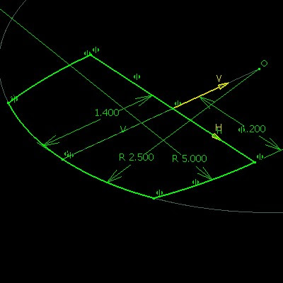
Orienting the Part: The idea behind conceptualizing is to determine how to approach your CAD model. Think about your part in a mold tool. What features does it have and how are they oriented? Can the part be oriented in the mold tool so that there are no undercuts?
By answering these questions, you can determine the draw direction and parting line for your part. Then you have a starting point for your CAD model.
 |
| Orienting the part |
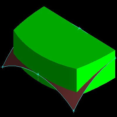
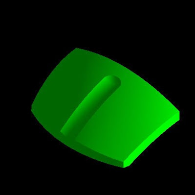
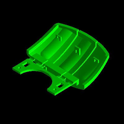
Modeling the Basic Shape: Many models begin by creating a Pad with a Sketch. 
ads

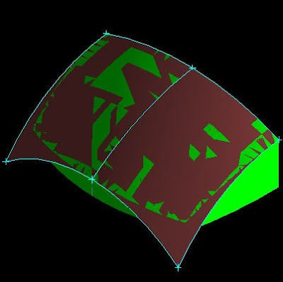
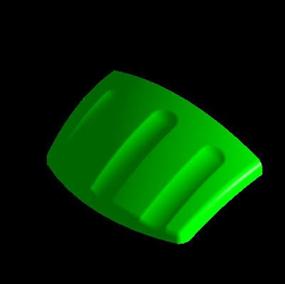
Shape your part by adding additional features. Creating sketches to define split profiles is a good approach. You can Pad or Shaft these sketches to Split the solid body.
You should already be thinking about draft. Adding Draft features while
creating the model in these early stages saves you time when you must prepare
your model for tool design.
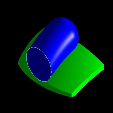
Padding sketches may not always define the desired shape. You may find it
necessary to create surfaces or additional solid bodies. Doing this allows more
flexibility in the way you can define the necessary shape. These bodies are
commonly referred to as tools. Use these tools to Split or Remove material away
from your solid body.
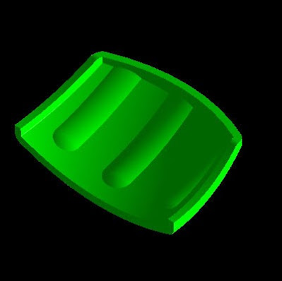
You also need to be thinking about Fillets. Use this feature to eliminate the sharp corners of your model. Fillets are normally added after Draft features.
By concentrating on only the basic shape of the part, you can now use the Shell feature to easily give the part a nominal, uniform thickness.
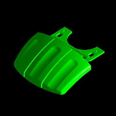
Adding Features: Now you can begin adding features such as snaps, ribs, and bosses. The reason for holding off on these features until now is that they typically have a thickness smaller than the nominal thickness. The Shell feature is used to define the nominal thickness, so these features should be added after the Shell feature.
Evaluating the Design: Once you have completed your model, you need to check it. You can use operations such as Measure Between to verify the thickness in different areas. Doing this gives you a chance to catch anything you might have missed. Correcting thickness problems allows you to avoid having to deal with sink marks after the part has started a test production run.
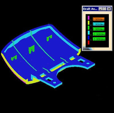
Draft Analysis is another key tool for analyzing your part. This allows you to graphically note the draft angles. It can be quite easy to forget to draft some faces of your model.

No comments:
Post a Comment